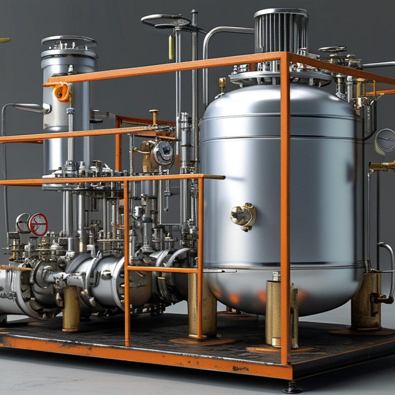
A Pressure Vessel Skid is a compact, engineered system that combines pressure vessels, piping, valves, instruments, and support frames. It is built for controlled installation and reliable operation. Instead of assembling every component separately at the site, engineers mount the equipment on a steel skid. The finished unit can then be transported, connected, tested, and commissioned more efficiently.
Inside the skid, a pressure vessel may store, separate, heat, or filter process fluids. Piping directs flow between the vessel and external equipment. Valves regulate isolation and pressure release. Instruments monitor pressure, temperature, level, and flow. A well-designed system should also include drains, vents, lifting points, and clear access for inspection. Small details matter. A misplaced valve can complicate maintenance.
Trevor Kletz, a respected process-safety authority, wrote, “If you think safety is expensive, try ignorance.” His warning applies directly to every Pressure Vessel Skid project. Design calculations, material selection, welding quality, pressure testing, and documentation cannot be treated as paperwork alone. They support real protection around stored energy.
The skid concept is practical, but it is not automatically safe. Poor layout, inadequate supports, or unclear operating limits can create serious weaknesses. Experience often reveals problems that drawings miss. This article explains what a Pressure Vessel Skid is, how it works, and why its design requires both technical discipline and honest review. Even a polished skid may need improvement. That is worth admitting.
What Is a Pressure Vessel Skid and How Does It Work?
A pressure vessel skid combines one or more pressure vessels, valves, piping, instruments, and structural supports on a common frame. It arrives as a tested process package, reducing field assembly and alignment work. In practice, operators may see a compact steel frame beside a pump, with gauges, drains, and relief devices arranged for access. The vessel is not designed by appearance. Its design basis begins with ASME Boiler and Pressure Vessel Code Section VIII.
Engineers define design pressure, design temperature, fluid properties, corrosion allowance, and cyclic service conditions. They then check shell thickness, head geometry, openings, weld efficiency, and external pressure resistance. ASME Section VIII, Division 1 commonly evaluates pressure parts using allowable stress rules. For hydrostatic testing, UG-99 generally requires a test pressure of at least 1.3 times MAWP, adjusted for allowable-stress ratios. Pneumatic testing commonly uses 1.1 times MAWP because stored energy is higher. These figures are design controls, not casual operating targets.
A credible skid review also considers transport loads, vibration, seismic forces, wind, thermal expansion, and nozzle loads. Relief-device capacity must match credible overpressure scenarios. Inspection records, material certificates, weld examinations, and pressure-test results support traceability. Field experience shows that small omissions matter. A poorly located drain can trap liquid, while an inaccessible valve can delay isolation. Engineers should verify the governing code edition and local requirements. The design is safer when calculations reflect actual operation, not only a clean datasheet.
| Data Dimension | Pressure Vessel Skid Information | Practical Design or Operating Consideration |
|---|---|---|
| Definition | A pressure vessel skid is a packaged assembly consisting of one or more pressure vessels mounted on a structural frame, together with piping, valves, instruments, supports, and related equipment. | The skid is an integrated package; the pressure vessel itself remains the primary pressure-containing component subject to the applicable construction code. |
| Primary Purpose | To contain, separate, filter, heat, cool, buffer, or otherwise process fluids under pressure in a compact, transportable arrangement. | The process duty determines vessel volume, internal components, connections, instrumentation, and operating sequence. |
| Applicable Pressure Vessel Design Basis | ASME Boiler and Pressure Vessel Code, Section VIII is commonly used for the design and construction of pressure vessels. Division 1 is widely applied; Division 2 may be selected for more rigorous design-by-analysis requirements. | The project specification, jurisdiction, service conditions, and purchaser requirements determine the applicable division and supplementary standards. |
| Pressure Boundary | Typically includes the shell, heads, nozzles, manways, flanges, tubesheets where applicable, and welded or bolted pressure-retaining connections. | Pressure-boundary materials and welds require traceability, qualified procedures, and inspection appropriate to the selected code and service. |
| Design Pressure | The maximum pressure used for mechanical design at the specified design temperature. It is normally established above the expected normal operating pressure. | Separate design pressures may be required for different chambers or for shell-and-tube equipment with independent circuits. |
| Design Temperature | The maximum and minimum metal temperatures used to select materials and calculate allowable stresses, thickness, and protection requirements. | Start-up, shutdown, depressurization, ambient exposure, heating, cooling, and upset conditions should be evaluated. |
| MAWP | Maximum Allowable Working Pressure is the maximum permissible pressure at a specified temperature based on the weakest pressure-retaining component and the applicable code calculations. | The completed vessel is commonly rated using the governing MAWP shown on the nameplate and design documentation. |
| Materials | Common material families include carbon steel, low-alloy steel, stainless steel, and other materials selected for pressure, temperature, corrosion, and process compatibility. | Material selection should consider corrosion allowance, hydrogen service, sour service, erosion, chloride exposure, and low-temperature toughness where relevant. |
| Vessel Configuration | Typical configurations include horizontal or vertical separators, filters, coalescers, accumulators, buffer vessels, reactors, and storage vessels. | Orientation and geometry affect drainage, separation efficiency, access, lifting, transport, maintenance, and plot-space requirements. |
| Process Flow | A typical sequence is inlet flow through an isolation valve, entry into the vessel for the required process function, outlet flow through downstream piping, and controlled drainage or venting. | Flow direction, residence time, pressure drop, phase separation, and allowable nozzle loads should be established during process and mechanical design. |
| Relief Protection | Pressure relief devices, such as safety valves or rupture disks, protect the vessel from overpressure caused by blocked outlets, fire exposure, thermal expansion, control-valve failure, or other credible scenarios. | Relief-device sizing and set-pressure selection must be based on applicable code requirements and documented overpressure scenarios. |
| Instrumentation | Common instruments include pressure indicators or transmitters, temperature instruments, level indicators, differential-pressure instruments, alarms, and shutdown devices. | Instrumentation provides process control, alarm functions, equipment protection, and information required for safe operation. |
| Structural Skid Frame | The frame supports the vessel and auxiliary equipment during operation, lifting, transportation, and installation. | Frame design should address static loads, operating loads, wind or seismic effects where applicable, lifting points, transportation loads, and equipment center of gravity. |
| Nozzles and Connections | Connections may include process inlet and outlet nozzles, vents, drains, instrument ports, relief-device connections, manways, and utility connections. | Connection size, rating, orientation, reinforcement, accessibility, and external piping loads must be coordinated across disciplines. |
| Corrosion Allowance | An additional thickness may be specified to compensate for expected material loss during the intended service life. | The allowance depends on fluid chemistry, operating conditions, inspection strategy, and the design life specified for the equipment. |
| Fabrication and Welding | Fabrication generally involves plate forming, fit-up, welding, heat treatment where required, machining, installation of attachments, and dimensional inspection. | Welding procedures, welder qualifications, nondestructive examination, and repair controls should comply with the selected construction code and project requirements. |
| Inspection and Testing | Quality activities can include material verification, visual examination, dimensional checks, radiographic or ultrasonic examination, liquid penetrant or magnetic particle examination, and pressure testing. | The inspection and test plan should identify hold points, acceptance criteria, test medium, test pressure, documentation, and authorized inspection responsibilities. |
| Hydrostatic or Pneumatic Test | A pressure test is performed after fabrication when required by the applicable code. Hydrostatic testing uses liquid; pneumatic testing uses gas and involves higher stored-energy risk. | Test planning must follow the governing code and approved safety procedures, particularly when pneumatic testing is considered. |
| Operational Sequence | The skid is isolated, inspected, and prepared for service; the vessel is gradually pressurized; process conditions are monitored; and the package is shut down, depressurized, drained, and isolated when required. | Operating procedures should cover line-up verification, venting, draining, relief protection, emergency shutdown, lockout, and confined-space controls. |
| Installation Advantages | Factory assembly can reduce field welding, simplify transportation as a single package, shorten installation time, and improve coordination of piping and instruments. | Transport dimensions, lifting limits, site access, foundation loads, and field tie-in requirements must be confirmed before fabrication. |
| Key Documentation | Typical records include design calculations, drawings, material certificates, weld maps, welding qualifications, nondestructive examination reports, pressure-test records, relief-device data, and operating instructions. | Complete documentation supports code compliance, commissioning, inspection, maintenance, and future modifications. |
It combines pressure vessels, piping, valves, instruments, and supports on one steel frame. The package arrives tested and partly assembled. Operators often see gauges, drains, and relief devices nearby.
Fluid enters through process piping and moves through controlled valves. Instruments monitor pressure, temperature, and flow. Relief devices protect the vessel during credible overpressure events. Controls may stop flow or isolate equipment automatically.
Engineers need maximum allowable working pressure, design temperature, flow rate, capacity, and fluid composition. They also review corrosion allowance, material strength, cyclic service, and testing requirements. Small assumptions can create large problems.
Pressure controls shell thickness, head geometry, openings, and weld requirements. Higher temperature can reduce material strength. Temperature also affects gaskets, insulation, expansion, and test planning. The datasheet may look tidy but still be wrong.
Capacity should identify both total volume and usable volume. Liquid service often needs vapor space above the liquid level. Gas service depends strongly on pressure and temperature. Do not treat every listed volume as usable.
Material selection should address corrosion, erosion, low-temperature brittleness, and cleaning chemicals. Fluid composition may change the expected damage mechanism. Material certificates support traceability. A standard material table cannot predict every site condition.
The vessel is filled with clean water and pressurized under controlled conditions. Calibrated gauges record pressure, temperature, and test duration. Inspectors check welds, flanges, drains, supports, and instrument connections. They look for leakage or distortion.
Compressed gas stores much more hazardous energy than water. A small leak can worsen during depressurization. Water reduces this stored-energy risk. Testing still requires restricted access and careful procedures.
Safeguards may include high-pressure shutdowns, low-pressure trips, emergency isolation, and automatic flow interruption. Each device should be tested under realistic conditions. A symbol on a drawing proves little. Unclear valve tags need correction before startup.
Poor drain placement can trap liquid inside low points. An inaccessible valve can delay isolation during an upset. Transport loads, vibration, wind, seismic forces, and nozzle loads also matter. I would recheck the flow rate; plant data often changes.
A Pressure Vessel Skid is a compact, engineered process package that combines one or more pressure vessels with piping, valves, instruments, and a structural steel frame. Its design is typically based on ASME Section VIII, ensuring that the vessels are selected and built to withstand defined pressure and temperature conditions. During operation, the skid may separate fluids, regulate pressure, provide overpressure relief, and measure or meter the processed stream in a coordinated sequence.
Key design inputs include the maximum allowable working pressure (MAWP), operating temperature, flow rate, required capacity, and material compatibility. These factors determine vessel dimensions, piping arrangements, component ratings, and protective devices. Before commissioning, the package undergoes inspections and pressure testing, including ASME hydrostatic testing at 1.3 times the MAWP where specified by the design and applicable requirements. Safety functions, shutdown logic, and protective instrumentation can also be structured around API 14C safeguards to help detect abnormal conditions and reduce operational risk.

 Hongke Qingneng